Meet Our New Hydraulic Test Stand: Part 1
After learning that Hydraulic Parts Source invested $250,000 to build a one-of-a-kind, entirely custom-engineered component test stand you may be asking:
- What is a test stand?
- What does it do?
- How does it test components?
- How is it controlled and used?
What is a Hydraulic Component Test Stand and What Does it Do?
A typical test stand comes equipped with a range of instruments and control systems that allow for precise monitoring and measurement of pressure, flow rate, temperature, and vibration, among other parameters.A hydraulic component test stand tests components to ensure they meet the required performance specifications and industry standards.
By subjecting the components to rigorous testing, test stands are used to identify any design flaws, manufacturing defects, or performance issues so the distributor or manufacturer can make necessary improvements or adjustments.
The data from each test offer full traceability. HPS will keep this data stored, ready to be made available upon request.

How Does a Test Stand Evaluate Hydraulic Components?
Pumps, motors, and a large variety of valves are the main components that make up a functional hydraulic system.A test stand provides a hydraulic power unit that generates the required pressure and flow, a control panel, and a series of valves, actuators, and sensors that simulate the component’s working environment.
Here is how each component gets tested:
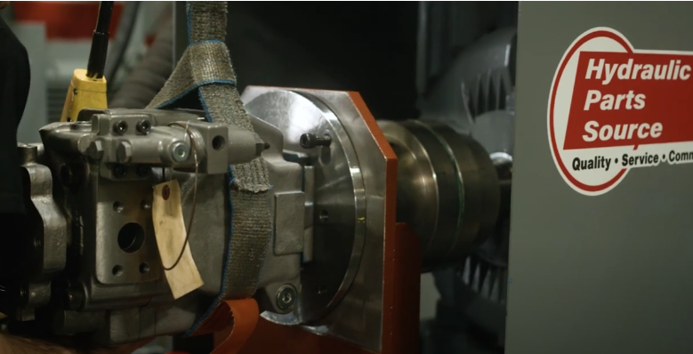
- Pumps are mounted on a universal mounting bracket. The physical connection between a pump and the stand’s motor is made with a universal driveshaft and adapters between the drive shaft and test pump shaft and oil from the reservoir. Discharge flow from the test pump is measured by a flow meter and restricted by a load valve before discharge flow is returned to the bench reservoir. Pumps are checked for efficiency at a rated working pressure and for external leaks.
- Motors are driven by a variable volume hydraulic pump on the stand. The test motor is mounted and connected in the same way pumps are tested. The motor's discharge flow is restricted with a load valve, putting the test motor under a workload. Motors are checked for efficiency at rated working pressure and for external leaks.
- Relief valves are pressurized and operated by the variable volume hydraulic pump on the stand. Flow returning from the valve is measured and the relief valve is checked for internal leakage, external leakage, “cracking” pressure, pressure setting, and resetting pressure.
- Four-way valves and valve banks are pressurized by the variable volume hydraulic pump on the test bench. The valve spool is shifted to a direct oil to a blocked valve port and leakage past the spool is visually checked at the non-pressurized adjoining port, then valves are checked for external leaks.

What Does the Control Panel Monitor?
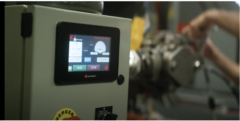
Control systems on a test stand allow for precise monitoring and measurement of pressure, flow rate, temperature, and vibration, among other parameters.A 5,000-psi pressure gauge indicates the operating pressure of a test pump. This gauge also indicates the test pressure applied to motors, valves, and cylinders being tested. This gauge also indicates the amount of load being applied to the discharge port of a motor when being used as a load pump when testing hydraulic motors. Pressure on this gauge is controlled by the test pressure control valve.
Here are a few other ways that the test stand’s control panel is used:
- A temperature gauge measures oil temperature and indicates if it exceeds 160° F
- Main pump pressure control regulates the operating pressure between 200 and 5000 psi
- A circuit selector valve is a two-position (either open or closed) valve located between the pump and the motor
This is a two-part series. For more information about our new test stand, and why it creates a superior quality worthy of the HPS lineup, see Part 2. Or check out our video at www.youtube.com/watch?v=CfqqrohAEVk
Tags
Posts
2024
August
2023
Need a Quality Supplier? HPS Checks All the Marks
[08/29/24 04:12 PM]
Digitization & Hydraulics
[08/29/24 03:45 PM]
February
Meet Our New Hydraulic Test Stand: Part 2
[02/15/24 02:50 PM]
Remanufacturing Benefits for End-Users
[02/01/24 03:04 PM]
January
December
2022
Hydraulic Systems and Their Components: An Overview
[12/20/23 12:27 PM]
Overfilling Hydraulic Fluid Can Cause Issues, Too
[12/08/23 01:18 PM]
November
Branded Gifts for Commuting Hydraulics Clients
[11/09/23 08:41 PM]
Diagnosing Pump Problems on Construction Equipment
[11/08/23 01:42 PM]
October
The Useful Complexity of Proportional Control Valves
[10/25/23 09:11 PM]
FAQs: Let’s Talk About Hydraulic Pumps
[10/23/23 08:25 AM]
Hydraulics System Corrosion FAQs
[10/11/23 01:00 PM]
September
August
5 Ways Inside Reps Can Boost Hydraulics Sales
[08/13/23 03:54 PM]
Positive Displacement Pump FAQs: How Do Hydraulic Vane and Gear Pumps Work?
[08/10/23 06:15 PM]
The Value of Hydraulic Pressure Relief Valves
[08/02/23 05:26 PM]
July
June
May
Hydraulic Parts Source is So Much More Than Pumps, Valves, and Motors
[05/30/23 12:09 PM]
How Does a Hydrostatic Pump Work?
[05/15/23 11:07 AM]
April
How Do Directional Control Valves Work?
[04/27/23 10:37 AM]
From Valves to Motion: Knowing How a Cylinder Works to Move a Hydraulic System
[04/14/23 10:23 AM]
March
HPS Troubleshooting Tactics: Common Hydraulic Valve Issues
[03/15/23 10:47 AM]
What Happens When Hydraulic Parts Suppliers & Distributors Join Forces?
[03/15/23 10:04 AM]
February
January
December
November
October
September
August
July
June
2021
Denison’s Innovative Beginnings Show Through in Quality, Flexible Parts
[06/20/22 06:38 PM]
Our Products: Get to Know True Blue Vickers
[06/06/22 06:30 PM]
May
Pascal’s Principle and the Origin of Hydraulics
[05/31/22 06:25 PM]
Avoiding Devastating Cavitation Damage
[05/03/22 06:16 PM]
April
Hydraulic Parts: How to Make Green Choices
[04/18/22 06:09 PM]
Hydraulic System Hazards: Avoiding Safety Issues from the Beginning
[04/05/22 05:58 PM]
March
Motors 101: Hydraulics at Work
[03/21/22 07:00 PM]
Valves 101: It’s All About Control - and Some Other Need-to-Know Facts
[03/07/22 06:53 PM]
February
January
December
November
2020
Promotional Gift Ideas for Fluid Power Distributors to Unwrap Marketing Potential
[11/29/21 10:00 AM]
Need-to-Know Fluid Power Facts: The 5 W's of Hydraulic Oil Viscosity
[11/29/21 09:32 AM]
How to Close the Sales Gap & Increase Revenue: Part 2
[11/08/21 08:06 PM]
October
September
August
July
June
Change Filter Elements to Avoid a Hydraulic System Nightmare
[06/07/21 05:02 PM]
5 Sources of Hydraulic Fluid Contamination (and How to Address Them)
[06/01/21 04:09 PM]
April
How to Win Back Lost Customers: 5 Steps for Fluid Power Distributors
[04/19/21 04:03 PM]
7 Outside Sales Strategies to Drive Fluid Power Revenue
[04/05/21 03:54 PM]
March
4 Reasons Fluid Power Distributors Should Consider Promotional Gifts
[03/16/21 03:48 PM]
Hydraulic System Corrosion: 3 Causes & 6 Prevention Tips
[03/10/21 03:42 PM]
February
Setting and Troubleshooting Relief Valves in Hydraulic Systems
[02/23/21 03:36 PM]
When & How to Replace a Hydraulic Pump Hose Assembly
[02/08/21 03:26 PM]
January
December
3 Directional Control Valve Problems & Fixes
[12/15/20 12:22 PM]
3 Ways to Align a Hydraulic Pump
[12/01/20 12:15 PM]
November
Why Are My Hydraulic Seals Failing? 6 Common Causes
[11/16/20 12:09 PM]
8 End-User Tips for Choosing a Hydraulic Fluid Power Products Distributor
[11/02/20 12:05 PM]
October
September
8 Checks for Restarting Hydraulic Pumps After Long Shutoff
[09/29/20 11:45 AM]
6 Key Hydraulic Product Distributor Strengths
[09/21/20 11:38 AM]
8 Things to Check When Your Hydraulic Pump Stops Flowing
[09/01/20 09:47 AM]
August
3 Common Causes of Noisy Pumps and What to Check
[08/17/20 09:34 AM]
Old Cores: The Key to New Revenue for Fluid Power Distributors
[08/03/20 09:01 AM]
May

