Hydraulic Parts Source is a premier supplier of remanufactured hydraulic pumps, motors, and valves, and we value what education we can provide for our customers, distributors, and end-users.
A standard practice in hydraulics is reading schematics.
A schematic is a valuable visual that maps how the basic elements function within a hydraulic system per circuit. Hydraulic circuits transmit and control power from a mechanical input (pump) to a mechanical output (motor) utilizing fluid.
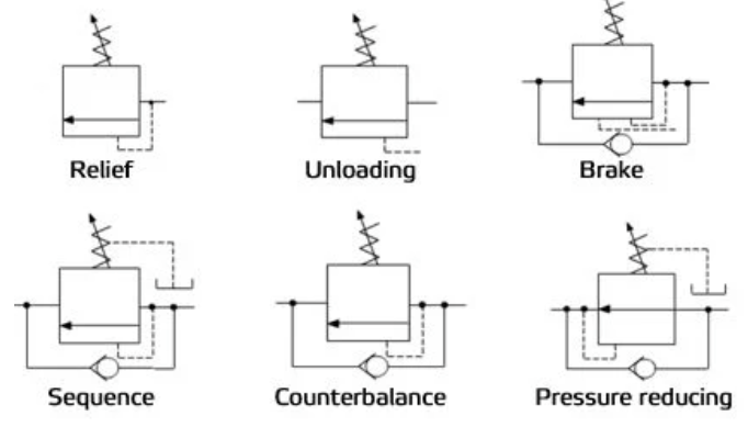
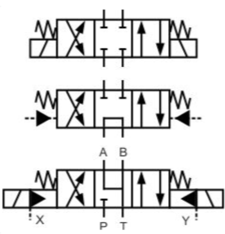
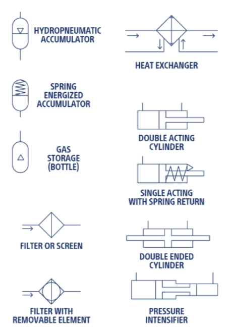
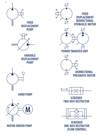
Before looking at a hydraulic circuit, it is important to reference commonly used graphic symbols for pressure control valves, directional control valves, actuators and accumulators, pumps and motors.
Pressure Control Valves
Directional Control Valves, 4 Way 3 Position
Accumulators & Actuators
Pumps & Motors
Putting Them All Together: A Simple Circuit
A schematic represents not only each circuit and component of the system but how each component behaves. Symbolic representation within each hydraulic circuit can be complex and daunting to a novice. But it doesn't need to be.
Let's start with the full picture, and illustrate how a simple circuit can appear in a schematic.
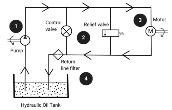
- The pump
- Valve(s)
- A motor
- Ancillary equipment, such as filters, heat exchangers, pipes, etc.
- Cylinders (not pictured)
What does this mean, and how do these components work within the system? Let's find out.
Pumps and Motors on the Schematic
Hydraulic pumps are one of the most necessary components in a hydraulic system, as they convert mechanical energy into hydraulic energy.
This hydraulic energy, in turn, results in more mechanical energy and powers the motors in a hydraulic system.
The input-output relationship of pumps and motors and knowing how to spot them symbolically on the schematic is vital to understanding the inner workings of hydraulic systems.
The pump-motor connection reveals information about the flow rate per shaft rotation. Motors are the prime movers used to rotate hydraulic pumps.
Motors are easy to spot, represented by the letter "M" inside a circle. A curved arrow (like in the illustration) represents the direction of shaft rotation.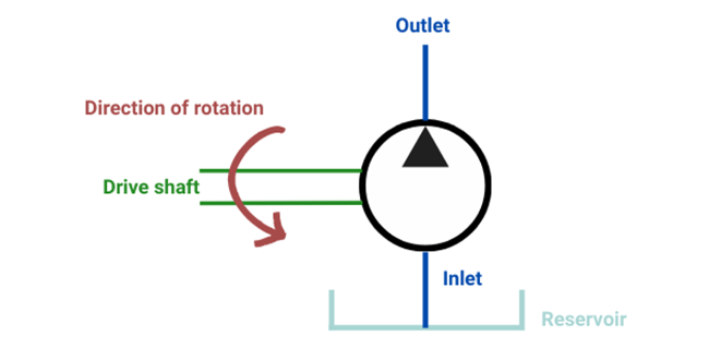
Hydraulic pumps do not look much different than motors on the schematic, as they are represented by a circle with a black triangle that points to which direction flow will go in. If the triangle is clear, it indicates a pneumatic pump (or compressor).
The lower end of the pump is connected to a hydraulic oil reservoir, and the upper end is connected to the remaining circuit. Just like with the motor, a curved arrow represents the direction of shaft rotations.
Hydraulic Valves at Work
As pumps and motors supply power and energy within a hydraulic system, valves are the mechanical devices used to control that power by regulating the flow of fluid.
Valve symbols vary depending on the type, as positions and behaviors may vary. They can be used to redirect pressurized fluid, control the level of flow to a specific area, or completely close a line.
Although dozens of varieties serve different purposes, let's look at how pressure relief, directional control, flow control, and check valves are represented on a schematic.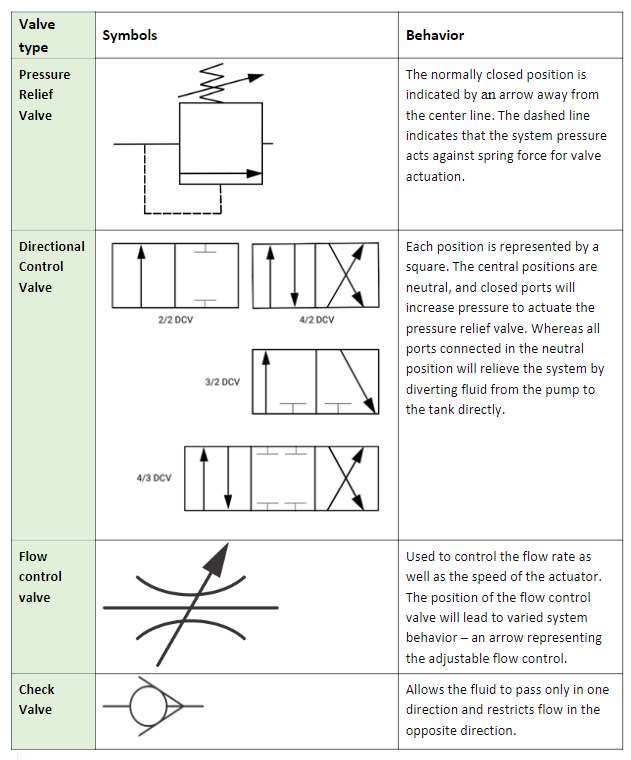
Why Learn How to Read a Schematic?
Symbolic representation within each hydraulic circuit can get complex, but knowing the basics is helpful when meeting the hydraulic needs of distributors, suppliers, and end-users.
Reading a schematic can help not only know how each circuit and its components behave within a system; it can reveal valuable information when troubleshooting, replacing parts, and providing.
From motors, pumps, valves, and beyond, the roadmap for knowing hydraulic systems and their circuits is at your fingertips once you can recognize the basics.
Hydraulic Parts Source is a leading fluid power remanufacturer, and we're ready to serve you. Contact us today to experience OE quality for a fraction of the time and cost by calling (888) 477-7278 or get a quote by emailing sales@hydparts.com.
